Calibration Patterns
For usage of calibration patterns in the API, see this guide.
Specifications
The position of the print is not aligned to the substrate. The printing process is conducted at room temperature without per-piece print calibrations or measurements. We therefore cannot provide any hard guarantees on the accuracy, but the following sections will outline what printing accuracy can be expected in general.
100 × 100 × 1 mm, 12 mm Grid Spacing
Optonic Part Number: 11248
Printed on a ceramic substrate of nominal thickness 1 mm
Accuracy of barycenters of dot grid
Relative deviation of distances of neighboring points: ≤ 0.1e-3
Absolute deviation of grid spacing: ≤ 1e-3
Thermal expansion: ~8e-6/K
Outer dimension tolerance: ±0.25 mm
Thickness tolerance: ±0.1 mm
200 × 200 × 3 mm, 24 mm Grid Spacing
Optonic Part Number: 11249
Mounting Kit Optonic Part Number: 13484
Printed on an aluminum composite material of 3 mm thickness
Accuracy of barycenters of dot grid
Relative deviation of distances of neighboring points: ≤ 0.1e-3
Absolute deviation of grid spacing: ≤ 1e-3
Thermal expansion: ~24e-6/K
Outer dimension tolerance: ±0.5 mm
Thickness tolerance: ±0.2 mm
390 × 390 × 4 mm, 48/96 mm Grid Spacing
Optonic Part Number: 13095 (48 mm), 13510 (96 mm)
Mounting Kit Optonic Part Number: 13476
Printed on safety glass substrates of 4 mm thickness
Accuracy of barycenters of dot grid
Relative deviation of distances of neighboring points: ≤ 0.1e-3
Absolute deviation of grid spacing: ≤ 5e-4
Thermal expansion: ~9e-6/K
Outer dimension tolerance: ±1 mm
Thickness tolerance: ±0.4 mm
Note
Thermal expansion is provided for reference only and is usually irrelevant in practical applications.
Dimensions
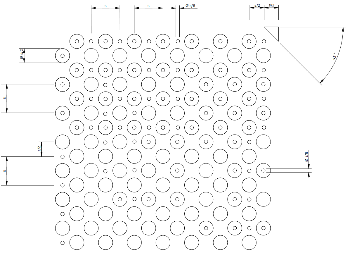
In the below images the dimensions of the calibration targets are given. The parameter \(s\) describes the grid spacing of the corresponding pattern.

