GPIO Port
(CR-Series)
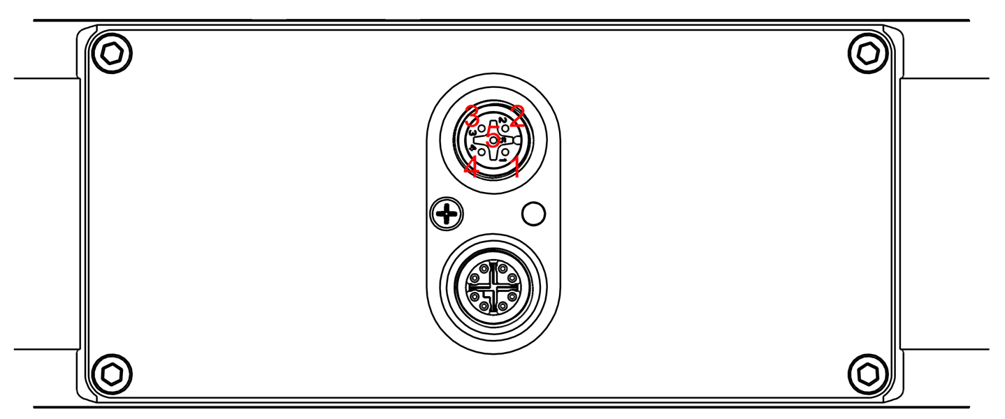
The GPIO port uses a 5-pin male M12 A-coded connector providing power input and trigger/flash input and output.
Note
The trigger and flash signals are ground referenced and push-pull driven.
Pin Assignment
1 |
Power Supply Input 24 V DC |
2 |
Digital Input, Trigger, 0 V / 24 V |
3 |
reserved, do not connect |
4 |
Ground (GND) |
5 |
Digital Output, Flash, 0 V / 24 V |
Electrical Characteristics
Digital Input
Switching threshold low -> high ~6.6 V
Switching threshold high -> low ~4.9 V
Digital Output
Voltage level low < 1.3 V
Voltage level high > DC_in–1.3 V
Maximum curent (source/sink) 20 mA
GPIO Wiring and Usage