First Steps with PartFinder
1. Select a Camera
Select and open the camera you want to use in NxView. For this guide, we will use the t_pipe file camera that is available on our website. Follow the guide on using sample data for more information on how to download and set up this camera.
Note that you will need an STL or PLY model of the parts you want to detect in the point cloud. For the t_pipe camera, such a model is provided on our website.
3. Create a Model
PartFinder uses a multi-step procedure that is explained in the command documentation. Following this procedure, we have to generate a model before we can use it to find parts.
Select your STL or PLY file.
If your model is symmetric or will only be observed from a certain direction, you can select the view point options accordingly. This is optional, but will improve performance for such situations. The
t_pipeis not symmetric, so we leave this at the default.You can leave the other options at their default values for now. If you want to experiment with them, see the command documentation or the tooltips in NxView for more information on what the different parameters do.
Choose a preset to define the detail of the generated template model - Try the ‘Fast’ or ‘Medium’ preset if your object has rounded surfaces or faces with different normal orientations constraining the 3D position of the model in the point cloud (like the pipe part in this example, a teapot, a computer mouse…) - Try the ‘Medium’ or ‘Accurate’ presets if one of the following is met
your object is small in the camera view field (e.g. more than 10 parts in each direction)
the object has very fine details to be matched (e.g. a cavity, hole, etc. which encodes the correct orientation)
the object is observed from orientations where it appears completely flat (like a box when seen from above, flat sheet metal parts, …).
Click
Create Model...to generate the model.
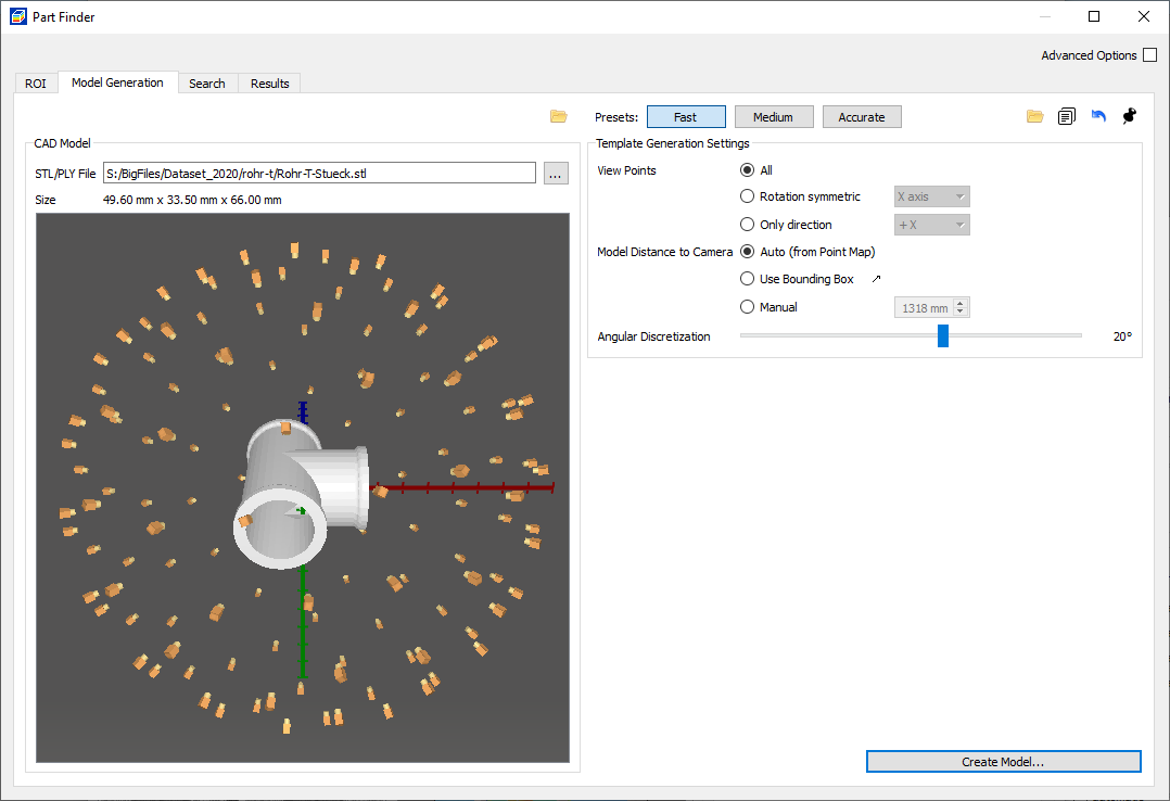
The model generation tab, where you can define the directions and density of the templates and 3D feature points.¶ |
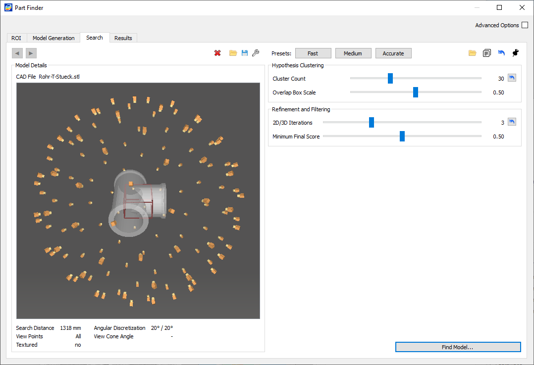
The search tab where you can select a loaded template model and set parameters for the search process.¶ |
4. Search for Parts
Switch to the
Searchtab in the part finder dialog.Set the Cluster Count parameter to the expected number of occurrences of the part. This parameter effectively limits the number of result poses PartFinder will return.
Choose a preset to guide the thoroughness of the search process - Try the ‘Fast’ or ‘Medium’ preset if your object is rather large and has no self-similar orientations - Try the ‘Medium’ or ‘Accurate’ presets if your objects is small or you need to resolve self-similar poses
Click on
Find Model...to start the search.Tune the Minimum Final Score parameter to find all occurrences of the model in the 3D data. Decrease the final score threshold if some parts are missing from the results, and increase it if incorrect results appear.
When the search is done, the dialog will show a table of detected parts in the result tab.
The detected parts will also be visualized in NxView’s 3D view. The color of the visualization indicates the Coverage of the match. Good matches will be green, worse matches (where e.g. some parts are occluded) will be orange.
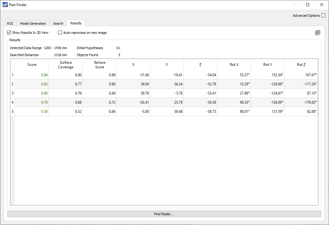
The result table with scores and positions of all detected parts.¶ |
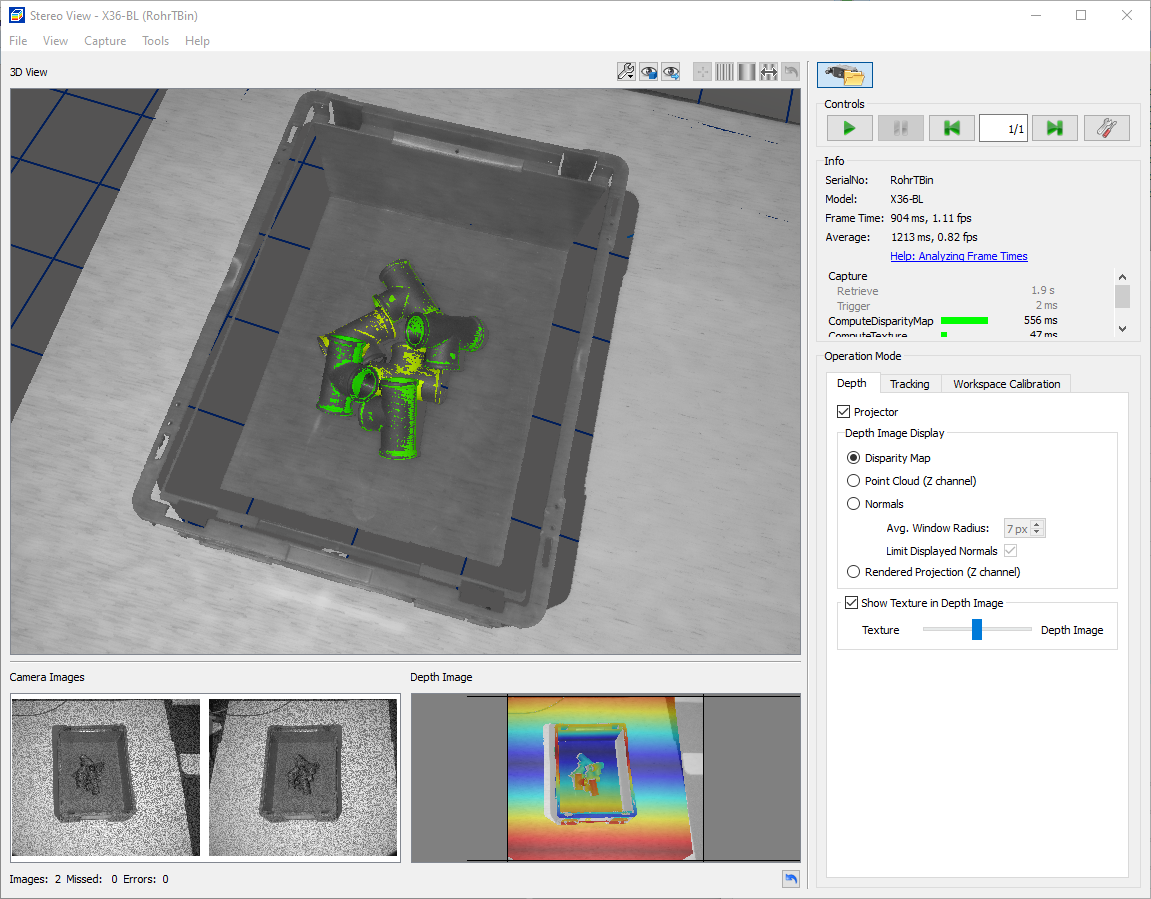
The detected parts visualized in NxView’s 3D view. The color indicates the score/quality of the match.¶ |
Troubleshooting Matching Results
You might use the provided presets to find a quick approximate solution for your matching process. The topics below give some advice how to improve matching for certain types of models.
Spurious Matches
Especially when using Viewpoints All it might happen that spurious results of small part surfaces appear in the result, which cannot be distinguished from correct matches by their Coverage percentage or Score alone. This is due to the fact that small templates, like a side view of a flat sheet metal part, or the frontal view onto a thin rod, have very few unique features. PartFinder can therefore map these templates into the depth and texture data at edges of flat surfaces with reasonably good scores.
To remove these spurious matches, try to reduce Viewpoints as much as possible to the actually occurring orientations. Please also check whether you can use the ComplementViewpoints, Angle and Symmetries parameters to reduce the set of templates to a minimum.
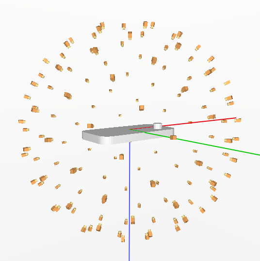
A sheet metal part with all viewpoints will like generate spurious matches with the templates observing only the thin sides of the part.¶ |
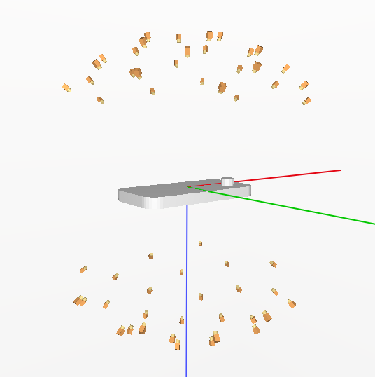
Removing the side viewpoints avoids spurious matches, and the part will likely not be standing on one of the thin sides anyway.¶ |
You might also consider setting the BoundingBox parameter to specify the search region and exclude locations of spurious matches.
All of these options will usually also yield significant performance benefits.
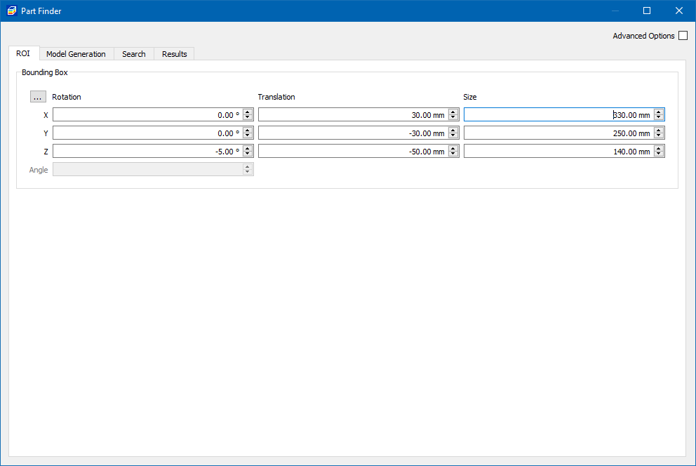
Definition of search region of interest in ROI tab of PartFinder dialog.¶ |
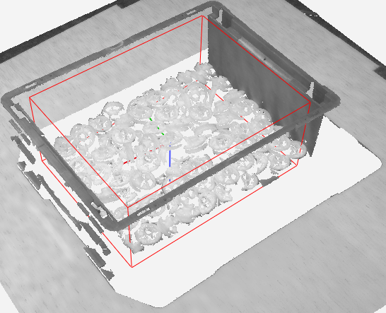
Visualization of search region in NxView main dialog.¶ |
Too Few Results
Check that you are not limiting the number of results by a too low cluster count value. Note that this is just an upper limit. The number of returned parts might also be lower, and you might need to set a larger number here to account for clusters in other locations of the scene, which will never return a valid match.
If you have very cluttered areas outside the actual search region, PartFinder might spend a significant amount of effort searching for parts where you know no parts will be. Consider guiding the search regions with a BoundingBox in this case.
Self-similar Part Orientations
If your part has self-similar poses which are not getting resolved correctly you can first increase the number of hypotheses which will be evaluated in each position. This will increase the likelihood that the correct orientation is contained in the cluster of each part, and the correct orientation will be returned in every location.
If the features distinguishing the correct from incorrect pose are small compared to the entire part size, the internal decision to output the hypothesis with higher score might not always be sufficient to select the correct orientation. In these cases you can specify a score region around the distinguishing feature. A score region is effectively a rotated box, positioned in the part coordinate system, which tells PartFinder to focus on texture and surface coverage in these areas, to decide which hypothesis in each cluster has the correct orientation.
Note that a too coarse model sampling distance or subsampling will also make it impossible for PartFinder to correctly judge the presence of small part features in the score, regardsless of the usage of score regions. Make sure to select a small enough model sampling distance such that multiple samples end up on the relevant features of the part, and a high enough subsampling factor so that the feature will be present in the subsampled depth and texture data.
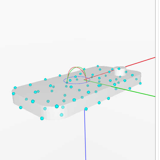
Too coarse sampling: only one 3D feature point hits the small cylinder feature which determines the orientation of the part.¶ |
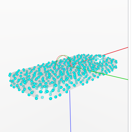
Sufficient sampling: multiple 3D feature points reside on the cylinder feature.¶ |
Insufficient Pose Accuracy
If your part has sufficient 3D geometry to constrain the part pose (surfaces with normals in different directions), you can likely improve the accuracy by lowering the model sampling distance. If your part is small in the image you should also check the subsampling factor and try to increase it.
If your part is mostly flat and its position is mainly constrained by 2D/3D edges, then increasing the number of refinement iterations or increasing the subsampling factor might help to improve the pose accuracy.
Note
It is worth having a close look onto your 3D point cloud as well! Improving the point cloud parametrization will directly improve PartFinder results. Check the guide for parameter adjustment and tune image exposure and median filter to have all part features and edges represented correctly and with minimal noise in the point cloud.
Gap-less Adjacent Parts
If parts cannot be distinguished by geometry alone it might help to prioritize the use of texture edges by setting coverage for the generation of the template model. This will down-vote matches where the camera’s texture image contains edges inside a surface of the part match, and instead prioritize matches where no texture edges are present within the surfaces.
Partial Observations or Deformed Parts
If your CAD model is larger than the portion of the part you can observe in the camera, or you want to explicitly focus the matching process to some smaller region of the model (e.g. because other regions of the part might be deformed and will not coincide with the CAD model), you can focus the matching process on these part regions using crop regions. The 2D and 3D features of the generated template model will then be limited to features in the specified regions of the CAD model.
Note
Please note that this is different from cropping the CAD model itself, because a cropped CAD model would introduce artificial edges at the cropping boundaries, which PartFinder would try to align in the matching process. These artificial edges will not be generated when using crop regions on a complete CAD model.

